Industrial Automation Using PLCs
I. Introduction and Requirements of Industrial Automation
1. Industries go through a certain process or processes to manufacture their products.
2. Process involve various physical and chemical treatments.
3. They involve control of physical parameters like speed, force and torque, power, energy, pressure, temperature, time etc.
4. Not only that the parameters are to be controlled, they have to be controlled in an appropriate sequence so that the process is effectively controlled.
5. In a process plant, engineers like the mechanical (thermal), metallurgical, chemical engineers are involved in the actual process know-how; electrical engineers are involved extensively in the control and the actual implementation of the process.
6. The electrical engineers have at their disposal, various electrical and electronic items – equipments, components as well as other electrically operated devices enabling them to implement, operate, control monitor and trouble-shoot the above process controls.
7. The normal devices are motors, motor control equipment, power on/off devices, types of solenoids, pumps, fans, compressors, heaters, refrigeration system etc.
8. The above are the work-horses or the equipment of the action in the control process. These actions are getting monitored through various sensors or transducers for the parameters like the speed, current, voltage, pressure, flow, temperature, position, time etc and if necessary modified. These modifications can either be on-off type or of continuous regulation.
9. All these methods need to be controlled as per an appropriate strategy or program which is unique for each process.
10. Also modifications are to be done to improve the process efficiency or changing the process for different product requirements should be done fast and effectively.
11. There must be methods to visually monitor whether the process is proceeding according to the desired requirements.
12. There must be trouble shooting methods in case of problems; There must be preventive maintenance methods.
13. Maintaining records of all the process issues as follows for a reasonable time.
- Process parameter logging.
- History of energy consumption.
- History of problem and solutions.
- History of revisions etc.
14. Other facilities as follows are also required.
- Process scheduling
 - Test schedules
- Maintenance Scheduling
- Energy consumption calculations.
The above form the requirement for industrial automation.
II. Typical Industrial Electrical Equipment:
The following are the various electrical equipment for the implementation of the Process. The actual items present will vary from plant to plant depending the individual requirements.
1. HT power distribution through HT breakers / isolators including their protective relaying and monitoring through CT-s / PT-s
2. HT cables and bus ducts.
3. Various Transformers including their protective relaying and monitoring.
4. LT cables and bus ducts.
5. LT power distribution and control panels.
- Power distribution boards with monitoring.
- Local isolation Transformers for voltage and fault level matching
- Motor control centers with starters for fixed frequency AC motors.
- Power conversion panels for variable speed drive panels.
- Output power distribution panels for individual motors
6. Various types of motors.
- HT AC motors and their starters.
- Main and auxiliary DC / AC motors ( for the VSD-s) as well as
- Fixed speed AC motors for conventional applications.
7. Other common electrical utilities like
- Pumps; - fans; - compressors; - heaters; - lighting systems,
- Material handling equipment like cranes etc.
8. Sensors
- Motor mounted devices called MMD-s
- Field mounted devices called FMD-s for instrumentation, feedback and controls.
9. Central relay and PLC based control panels for (earlier these functions were carried out by relays; now they are extensively carried out by PLC-s)
- Providing power suppliers for all the PLC inputs and outputs as well as other devices, sensors, solenoids and such actuators.
- For process sequencing
- Fault monitoring and protection
- Special REAL TIME controls like coordinated controls.
- Communication networking for the 1) control signals and 2) Information signals through separate control bus and information bus.
- Fault annunciation. requirements
- Status annunciation requirements.
- Human Machine Interface terminals for Total mill visualization and controls (these are normally located in the control pulpit for the operator’s requirement)
- Event history recorders and Data loggers.
10. Control desks and posts with PB-s, Lamps, selector switches, meters, LCD panels as well as HMI-s for total mill visualization and controls.
11. Other miscellaneous items like, UPS, CCTV-s, fire alarm, lighting, material handling cranes, communication systems etc.
III. Functions of Central relay or PLC based control panels:
1. They form the central set of control, interlock and protection panels.
2. In earlier days, with relay panels the exchanges were related to mainly commands and status ( called discrete or digital signals) only. With PLC, these signals can now be either digital or analog (control values or variables). The analog set points or feedbacks can also be processed as required.
3. They interface with all other equipment in the plant and exchange various signals as enumerated below
i) For HT panels the status indication, fault annunciation, feed back information for instrumentation such as input voltage, current, pf and energy input.
ii) For transformers, the status, temperature figures, fault annunciation etc.
iii) For PDB-s, status indication, voltage current and pf feedback and hence the energy of a section.
iv) For drive control panels the relevant signals are, status signals, healthy signals, on/off command, forward/reverse commands, fault annunciation, voltage, current speed and such relevant control parameters and also the required generation of the appropriate reference signals.
v) For MCC-s the on/off, forward/ reverse commands, fault annunciation and other relevant indications.
vi) For motors, signals related to temperature, cooling, motor protection relay inputs, insulation levels and also vibration level signals.
vii) With utility panels, they ensure proper operation of these equipment and they receive status of hydraulic, pneumatic and water utility systems of the plant like, pressure, flow, temperature, on/off conditions and if required redundancy operation for reliability.
viii) For MMD-s and FMD-s the various feedbacks and status signals are received. The required power supplies for these are also provided from these panels.
ix) The central relay and PLC based control panels interface with the devices in the control desks in control pulpits like the various PB-s, switches (on / off or selector type), lockable selector switches, mushroom head PB-s, foot operated switches etc. for the inputs or commands and with the lamps, PB lamps, meters, hooters etc for the outputs. Most of these devices are oil tight types. Also HMI is normally mounted in a control desk for the human machine interface with PC-based SCADA for visualization and control with industrially ruggedized PC and membrane type keyboard. In older control pulpits individual fault annunciation windows on the panels used to be always present ; In the present day plants these are only provided optionally as these functions can be provided in the HMI PC itself.
Thus the relay and PLC based control and protection panels interface with all the mill equipment and functions and hence is truly a central panel. The enclosed drawing provide both the power flow and the signal exchange flow with this central panel in a typical plant.
IV Relaying Functions of the Conventional central relay and control panels or called the mill interlock panels
The conventional central relay and control panels generally provide the relaying ( sequencing ) functions only. In addition they are used for contact multiplication for distribution of the commands and outputs.
1. Industrial Relays
Even though PLC-s have replaced the relays effectively, the knowledge of the elector-mechanical relays are necessary because they are still used for contact multiplication, voltage and current matching of the output etc. along with the PLC I/O-s themselves.
i. Relays have coils with appropriate windings wound on a hollow former through which the plunger moves when energized. The moving contacts are connected to the plunger. The coil is energized by a DC or AC voltage. 24V DC, 110V AC, 220V AC are some of the standard voltages.
ii. The relay can be individually front mounted with the coils and terminals accessible from front or socket mounted with the wiring done to the socket.
iii. The DC relay coils are normally connected with a free wheeling diode across the coil. This provides protection to the coil against high voltage breakdown, when the coil current is interrupted.
iv. The contacts are N/O or N/C type or C/O type. The individual front mounting type relays have normally 2 N/O + 2 N/C contacts. Sometimes additional contacts can be added to the basic relay.
v. In the socket mounting type relay, the contacts are C/O type, with one pole and 1NC and 1 No contacts. Normally 3 C/O contacts are present in such a relay.
vi. If more contacts are required to implement a logic may have to add additional contact multiplication relays. This is one of the major disadvantages of the conventional relay panels. Physical contacts must be present for each function. In contrast in the PLC panels the status of the input or output ( called input and output images ) or intermediate flags can be used any number of times as these are soft signals when implementing the logic
vii. The relays for the logic build-up can be same type with minimum current rating. However the relays for the outputs be selected such that the contact current rating should take care of the load current.
viii. The relays along with their contact blocks can be wired in such a way that the appropriate sequencing is taken care of.
2. Timing Relays
i. Till recently it was implemented using a pneumatic timing head which was getting added to a relay to provide the time delays.
ii. This time delay could be during on-time or during off time or some times they are with on/off time delays.
iii. Now a days solid state timers are available for use and pneumatic timers are hardly in use.
iv. The timer relays are normally provided with adjustment for setting the time delays.
The above relay contacts ( under 1 and 2 ) go back to the normal conditions when the power is disconnected or made off.
3. Latching or memory relay
• This has got 2 coils – one latching coil and the other un-latching coil.
• The latching coil when energized , closes and latches the relay by a mechanical means. With this, the relay maintains its position even when the power is off.
• To de-energize the relay, a de-energizing coil need to be momentarily energized.
4. Mechanically latched type
These are two individual relays with an additional mechanical latching arrangement to ensure that when one relay is on, the other is necessarily off. One will not be able to energize the second relay. This will be useful for applications like forward / reverse control of a motor where only one function is normally required.
The above discussions on relays provide the idea of control functions which can be executed with the conventional relay panels and which need to be executed when PLC-s are used.
These conventional panels are built up depending on the logic to be implemented after the mill builder provides the overall operational method which is elaborated further by the electrical supplier as per the actual implementation.
While the functionality of the mill interlock panel is similar in the PLC panels, the concept defining the number of inputs and outputs came into the use with the implementation with PLC-s.
V PLC based control and inter lock panels
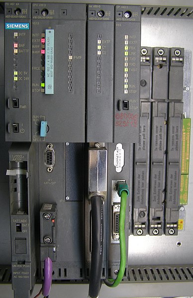
As compared to the central relay and interlock panels or mill interlock panels , the modern day PLC based interlock panels are able to handle much more of functionalities as explained under III . Since the PLC-s themselves are micro- processor or controller based they have the same working architecture like the standard computer architecture with the following elements. They are the i) Central processing unit or CPU-s along with their hard-ware, firm-ware and application software, ii) memory iii) communication with other PLC-s, HMI-s , other devices etc. iv) power supply as well as the racks with back plane for mounting the cards and the v) inputs and vi ) outputs. The inputs and the outputs form the bulk of the hardware depending on the plant requirement and capacity.
While the PLC CPU, instruction sets, software, memory, communication and other capabilities . are dealt with separately under the next section, this section deals with inputs and outputs. Apart from the functions involving Boolean logic ( normally done by electro-mechanical relays ), PLC-s handle many other functions like, counters, timers, real time clock, communication with other PLC-s and devices, handling math functions etc. The functionalities differ from PLC to PLC. The appropriate and optimal type has to be selected to address the application requirements and to get the best value for the cost.
Apart from the functionalities , the PLC type is primarily decided based on the number and the type of inputs and outputs.
The defining of the inputs and the outputs got into the use with the use of PLC-s for the control and interlock functions. This is because in the PLC panels the status of the inputs or outputs ( called input and output images ) or intermediate flags can be used any number of times as these are soft signals when implementing the logic. The advantage of this method is that even at the beginning of a project ( even during the cost estimation stage ) one can estimate the number of inputs and outputs and decide the type of the PLC. One need not even be fully clear about the logic or the total functionalities to estimate the PLC-s.
An example for selecting the number of inputs and outputs is given in one of the following sections . The types of industrial inputs and outputs are discussed first .
1 Input Devices:
1.1 Push Buttons:
They are the commonly used input devices They have basically two parts – operating buttons (actuators) and the contact units. The contact unit can be N/O or N/C types;
i. Normally 2 N/O and / or 2 N/C contact blocks are common when used with the conventional relay based control panels. With PLC based system, the input block need only be 1 N/O or 1 N/C. This input along with their complement can be used any number of times in the PLC ladder diagrams .
ii. The operator buttons are of different types; i. flushed or extended head ii. Mushroom head
iii. The buttons are normally with different colours, like the indication lamps to be described under the outputs. Green is normally used for ‘on’ functions and ‘Red’ is used for ‘off’ function; other colors like yellow, black etc are used for other functions like start, stop, jog, thread etc. functions.
iv. Sometimes the mushroom headed red coloured off (emergency) PB actuators get mechanically latched when pressed; They need to be turned in one direction to release the same.
v. Sometimes other types of actuators replace the conventional push button heads, like the following : i) locking type (through key )PB actuator ii) selector type push button actuators ; They are selected for certain locking type control functions like enable / disable or forward / reverse selection type respectively.
vi. Some times the PB actuator unit has a transparent head(with appropriate coloured lens) with in built indication lamp, apart from the contact blocks. This can be used for an application like starting a motor by processing the PB which initiates closing a contactor for starting the motor and at the same time provide a feed back through this contactor auxiliary contact block (a N/O contact getting closed) which lights up the inbuilt lamp in the PB head. These are called PB lamps. For a PB lamp, the lamp will be fed as the output of a relay or PLC.
vii. Push buttons are extensively used as input devices for the control relay and PLC panels giving the required ‘operator commands’
1.2 Limit switches:
These are normally used to sense the reaching of the required physical limit by a machinery or a motion control system. On reaching the required limit, the limit switch closes and provides an input to the central relay and PLC panels for initiating an action;
eg stopping a motor or reversing an operation etc. The following types limit switches are there:
i) Mechanical / lever type limit switch :
The limit switch operates on physical contact and closes a switch provided with N/O and N/C contacts.
ii) Rotary programmable cam limit switches:
Here the rotary limit switch arrangement is coupled to the motor or the actual load shaft driving an operation. The coupling is through an appropriate gear box so that for number of revolution on the equipment shaft side, the limit switch shaft rotates once. On the limit switch shaft are number of cams and the cam actuation positions are set at the required appropriate angles. These cam settings are adjustable programmable. With this arrangement the individual cams operate the associated limit switches. The operation of these limit switches can be associated with the reaching of appropriate limits in a linear travel; eg. travel of a cage (carriage) carrying the ore and other materials into a blast furnace. At the various operations of the limit switches various functions as follows can be initiated :
Position i. Bottom position – start at low speed
Position ii. Acceleration to full speed
Position iii. Signal to small bell to open
Position iv. Signal to close small bell
Position v. Deceleration to low speed
Position vi. Stop ; top position for tipping the material into furnace.
iii) Rotary programmable encoder type limit switch:
This functions exactly like ii) but this is done by counting of the pulses generated by the encoder and comparing the accumulated count with the preset counts. This type is much more flexible as compared to ii) and is easily settable. However they require external power supplies.
iv) Non-contact type proximity switches:
1. They also function as limit switches but without physical contact.
2. There are two types – called inductive proximity switches or capacitive proximity switches which operate due to changes in the magnetic field or the capacitance value under the proximity of the part or item being sensed. These switches also require external power supply and the outputs are normally open collector transistor type to which an external relay can be connected or can be a direct input to PLC input card.
3. These proximity sensors can also be used to measure the speed of a motor or drive by non-contact method.
1.3 Other type of sensors
Other type of sensors include rotary pulse tacho-generator (incremental encoder) for speed measurement, absolute encoder for position measurement, light sensors, ultra sonic linear velocity sensing unit, temperature measuring sensor, pressure measuring sensor, flow measuring sensor, on-off type (discrete levels) temperature monitor , pressure monitor, flow monitor etc.
Of the above mentioned inputs, many of them are on/off type (either potential free contacts or open collector type) and are called as digital inputs and some of them are providing analog inputs for continuous controls.
There are also other soft inputs like the keyboard inputs etc. but they do not form hard wired inputs.
2. Output devices:
The above mentioned devices are input devices for a relay and PLC control system. There are also number of output devices which get connected to a relay or PLC based control system. They are as follows:
2.1 Contactors
i. The functioning of contactors are similar to relays; Additionally contactors have 3 or 4 power N/O contacts (normally) which is used to switch on the power.
ii. The contactor coils are energized through PLC output or another relays contact and through the coil power supply (110VAC, 220VAC, 415VAC etc). DC supplied coils are also present some times.
iii. The contactors are normally used to switch 3 phase AC power to say a motor or a power modulator or such an application and they are extensively used.
iv. Contactors are normally available in various sizes (size 0 to size 16 – corresponding to 16 A to 630 A and more).
v. Most of the contactors are for AC power switching.
vi. There are also DC power switching contactors available. They require special arc- chutes for lengthening the arc.
vii. Hence these DC contactors are more expensive and need to be carefully selected.
viii. All contactors have auxiliary contacts for inter locking and relaying functions. Normally 2 No + 2 N/C contacts are provided for these auxiliary functions.
ix. Even though relays, times etc. are replaced by the soft logic of PLC to undertake logic function, the contactors continue to be used for feeding the final load like a motor etc. Hence the contactors are normally on-off devices for the other electrically operated equipment and hence it is essentially an output device. Only their auxiliary contacts take part in the relaying functions.
x. Apart from the selection of contactors to match with output load current and voltage, they need to be selected, also considering the numbers of operating cycles per hour.
2.2 Solenoids
i. Like a relay and contactor, the solenoid is an electro-mechanical device. In this the electrical energy is used to magnetically cause a mechanical movement.
ii. The solenoid; like the contactor has a frame, plunger and the coil. The coil is energized by AC or DC voltage. Upon the application of the voltage to the coil, the corresponding plunger is pulled back through a spring in case the coil voltage is interrupted.
iii. The AC solenoid draws a large in-rush current on energizing, when the plunger is fully out. The current drops to minimum value when the plunger is fully in. Due to this, it is important to ensure that the solenoid is fully energized i.e. the plunger is fully in. Otherwise the solenoid coil will take more than rated current continuously resulting in the burn-out of the coil.
iv. As against this, DC solenoid takes a constant coil current; but AC solenoid has superior initial pull.
v. For many industrial applications, 24V DC solenoids are normally preferred.
vi. While the contactor as output devices are selected based on the load current and voltage requirement, the solenoids are normally selected to handle appropriate pressure, force or weigh to be lifted etc. Accordingly the solenoid size varies.
vii. Depending on the application, there are different types of solenoids
1. Single solenoid (with one motion) with one coil. When it is energized it moves against the spring and when de-energized comes back to original position.
2. Single solenoid (with one motion) but with two coils. This is similar to above but with latching feature. One coil is for switching on and another is for switching off.
3. Double solenoid (with two motions, say up / down) and with two coils. When one coil is energized, the motion is upwards and downwards when the other coil is energized. It goes to neutral position when both the coils are not energized.
4. As it can be understood the number of coils to be energized decide the number of outputs per solenoid to be considered by the PLC.
5. There are different types of solenoids available like solenoids for gas, for lubricants, for water or for emulsion (water + oil) etc and depending upon the application or the force the type is selected.
2.3 Proportional solenoids / solenoid valves:
Normally the above solenoids are on/off devices; some times it is required to provide a motion which is proportional to the supply current amplitude. They will be normally supplied with currents in the range of 4 mA to 20 mA for opening a valve from 0% to 100%. Proportional valves are used in a closed loop systems to correctly adjust position, pressure/force of a control system eg for automatic gauge control of a cold rolling mill.
There are also continuously adjustable devices – e.g screw down in a rolling mill, measuring gauge adjustment for a cut length etc which are controlled through a proportional control system based on electrical motors or hydraulic valves .
2.4 Other output devices
Apart from the above, there are number of other output devices, such as air / oil / gas circuit breakers, clutch with a coil for mechanical equipment like shears, brake and brake coil for stopping the machine precisely, magnetic lifts etc.
Other commonly used outputs are indication lamps with different colours ( like the colours for the input PB-s ), fault annunciation windows, hooters and howlers for the faults, various indication meters.
Of the above mentioned outputs, many of them are on/off type ( through either potential free contacts or open collector type outputs ) and are called as digital outputs and some of them are providing analog outputs for continuous controls.
There are also other soft inputs like the keyboard inputs etc. but they do not form hard wired outputs.
The above discussions provide information on the various types of inputs and outputs seen by a PLC.
3. PLC inputs and outputs : For a PLC, normally there are separate input and output cards ( there are also mixed type of cards having both inputs and outputs ); these cards are normally with number of inputs or outputs –for 8 or 16 or 32 digital inputs or outputs and 4 or 8 or 16 analog inputs or outputs. All the digital inputs are normally opto- isolated and analog inputs are either single ended type or the differential type. The differential inputs have better noise immunity. The digital outputs are normally open collector type; some of the digital output cards have potential free contacts of a relay. Similarly the analog outputs are single ended or differential type.
Most of the input and output cards are suitable for 24 V DC power supplies. This is the most preferred power supply. Other voltages like 110 V DC or AC are also common The analog input and output cards are capable of accepting and providing ± 10 V inputs and outputs respectively.
These cards are generally located in the racks. Low end PLC-s have brick type construction and are DIN-Rail mounted. Some of the micro PLC-s are available in a compact version as a single module with all the functions interconnected. They can be in the main PLC rack itself or in the extension racks located in the PLC panel exclusively for these I/O-s. These input cards access the PLC in the parallel mode and hence their access times are quite small. Normally all the inputs and outputs which require fast access are located in the PLC or their extension racks. Similarly all time critical analog inputs and outputs are normally located in these racks. These I/O-s are called parallel I/Os.
While the main PLC rack will be located in the control room with controlled ambience – dust free and at controlled temperature , the I/ O-s can also be located all over the plant. These are called remote I/O-s. These are located in the vicinity of an area where there are number of I/O-s. E.g in the pulpit there will be number of I/O-s and they are terminated into a panel or box which house the remote I/Os. These are also located in the racks. But they are different from the racks in the PLC panel. They are called remote racks with their own separate power supplies etc. This arrangement helps to minimize the length of cabling for majority of the I/O-s in the plant. From the remote rack, only a single serial cable communicates with the main CPU in the PLC room through special remote communication cards at both ends at speeds of the order of 56 or 112 KBPS . Since the remote I/O-s communicate over the serial cables the response or through-put of these I/O-s will be slower than the parallel I/O-s.
Depending on the application, the PLC I/o racks are to be selected ( parallel type or remote serial type ) and used considering the saving in the cabling cost on one hand and the required responses on the other hand.
4. Selection of the PLC based on inputs and outputs :
i) PLC as a standard programmable controllers are being offered by many important multinational electrical product companies such as i) General electric company of USA, ii) Siemens, iii) ABB iv) Alstom v ) Allen Bradley ( Rock-well automation) vi) Mitsubhishi vii) Hitachi and some other companies. In India Siemens and Allen- Bradley PLC-s are the most popular. All these companies have range of PLC-s from micro PLC-s ( addressing less than 10 digital inputs and 10 digital outputs for simple sequencing ( Boolean ) capabilities ) to high-end large scale PLC-s ( addressing more than 10 K inputs and outputs – both digital and analog types-and with complex instructional capabilities and handling high speed calculations involving real or floating point values ).
i. The I/O-s (which as mentioned earlier) form the bulk of the PLC hardware, are decided based on the motor and component list normally prepared by the machine supplier or mill builder.
ii. This is the starting document for deciding the specification of all the electrical equipments. Refer the enclosed ‘typical motor & Component list’.
iii. This list provides information such as:
1. Name of the application and its 5 No of the mechanical supplier.
2,3. Quantity and type of motor or other actuator required – DC separately excited, AC slip ring or AC squirrel cage, single solenoid, double solenoid etc.
4,5. kW and RPM of the motor.
6. Duty class of operation S 1 to S 9
7,8. Mounting, protection class and cooling method for the motor and make.
9. Input voltage supply available or preferred like 3 ph, 415V, 50Hz etc.
10,11. Type of control of the motor- Reversing / non-reversing etc and quantity of power circuit.
12. Open loop or closed loop etc.
13. Location of the controls.
14,15. Quantity and types of other accessories (sensors and transducers like proximity switches, infrared sensors, light sensors, pressure transducers) etc.
16. Remarks
iv. The above information is used to decide the final number of I/o-s for the Mill automation.