Orifice plates
This method is based in the phenomenon that a stream of fluid (liquid, gas or vapour) when passing through the restriction or primary device (orifice plate, Venturi plate, flow nozzle, etc.) is subjected to the change of kinetic and potential energy of the stream during variations of flowrate. Figure 6.1 shows an orifice plate.
Let’s consider two cases with incompressible and compressible fluids.
Case 1. Incompressible fluid.
The following assumptions should be considered when derive working equations:2 - fluid flow is steady and frictionless, ie. there are no energy losses due to friction;
3 - flow is isothermal, ie. no heat losses or gains due to heat transfer between the fluid and its surroundings;
4 - there is no in and outflow of energy between sections A - A and B - B;
5 - mass flowrates in each cross-section of the stream is constant;
6 - pipe is horizontal.
An equation for conservation of mass flowrate is as follows:
then, we can give an equation for conservation of volumetric flowrate
When a volumetric flow rate in a pipe (see Figure 6.2) increases, then the velocity of the fluid through the orifice should increase as well. Since SA>SB , then vA<vB. Due to inertia the smallest cross-section area of the stream is not in the plane of the orifice itself, but some distance downstream from it. The total energy of the stream is equal to the sum of its kinetic energy and static head of the stream.
Equations for potential and kinetic energies of the fluid stream and work performed by it are as follows (from Bentley J. P. Principles of Measurement Systems, Longman, 1995, p. 280):
Combine equations (6.4) - (6.5) and get an equation for the conservation of the total energy per unit mass of the stream for the case of two cross-sections A - A and B - B:
From equation (6.9) we can get an expression for the velocity of the stream in the cross-section B - B:
Case 2. Compressible fluid.
In this case the density of a fluid depends on pressure in the form (from Bentley J. P. Principles of Measurement Systems, Longman, 1995, p. 287):
Therefore, mass flowrate is used in gas metering. A theoretical equation for a compressible flow has the following form:
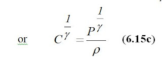
A practical equation for a compressible flow has the following form:
where, the expansibility factor has the following form according to BS 1041 and ISO 5167 (from Bentley J. P. Principles of Measurement Systems, Longman, 1995, p. 288):
Discharge coefficient data for orifice plate, BS 1042.
The Stolz equation:a). Conditions of validity for corner taps:
To calculate the value of Dor one need to perform several iterations until this value is obtained with the accuracy equal to the tolerance δ of machining of the surface of an orifice.
Step 1. Calculate Re.
Step 2. Set initial guess for parameters as follows: C=0.6, ꜫ =1.0 , E=1.0
Step 3. Calculate area Sor of the orifice hole using (6.13) or (6.23) and value of maximum flowrate.
Step 4. Calculate Dor.
Step 5. Calculate β.
Step 6. Revise the value of E according to

Step 7. If we have liquid, then ꜫ =1.0. Evaluate C according to (6.25). Then continue starting from step 3, and so on.
Step 8. If we have gas, then if
 evaluate ꜫ according to (6.24). Evaluate C according to (6.25). Then continue starting from step 3, and so on.
Step 9. Check if Dor. >=12.5mm .
Step 10. Check if final values of β and Re are within limits.


