Custom Search
RECENT POSTS

Sunday, December 19, 2010

What are Electrical Transducers?


                          The transducers that convert the mechanical input signals of the physical quantity into electrical output signals are called as electrical transducers. The input given to the electrical transducers can be in the form of the displacement, strain, velocity, temperature, flow etc and the output obtained from them can be in the form of current, voltage and change in resistance, inductance and capacitance. The output can be measured easily and it is calibrated against the input, thus enabling the measurement of the value of the input.

Here are some of commonly used electrical transducers:

1) Potentiometers: They convert the change in displacement into change in the resistance, which can be measured easily.

2) Bridge circuits: These convert the physical quantity to be measured into the voltage.

3) Wheatstone bridge: It converts the displacement produced by the physical quantity to the current in the circuit.

4) Capacitive sensors or Variable Capacitance Transducers: These comprise of the two parallel plates between which there is dielectric material like air. The change in distance between the two plates produced by the displacement results in change in capacitance, which can be easily measured.

5) Resistive sensors or Variable Resistance Transducers: There is change in the resistance of these sensors when certain physical quantity is applied to it. It is most commonly used in resistance thermometers or thermistors for measurement of temperature.

6) Magnetic sensors: The input given to these sensors is in the form of displacement and the output obtained is in the form of change in inductance or reluctance and production of the eddy currents.

7) Piezoelectric transducers: When force is applied to these transducers, they produce voltage that can be measured easily. They are used for measurement of pressure, acceleration and force.
Industrial Piezoelectric transducers


8) Strain gauges: When strain gauges are strained or stretched there is change in their resistance. They consist of the long wire and are able to detect very small displacements produced by the applied force or pressure.

9) Photo electric transducers: When the light is applied to these transducers they produce voltage.


10) Linear variable differential transformer (LVDT): LVDT is the transformer consisting of the primary and the secondary coil. It converts the displacement into the change in resistance.

11) Ultrasonic Transducers: These transducers use the ultrasonic or ultrasound waves to measure parameters like fluid level, flow rate etc.
Ultrasonic transducer

Apart from these there are some more electrical type of transducers like moving coil type, changing dielectric type, changing core positions type etc.

Article Source: http://www.brighthub.com

Read more...

Types of Transducers : Mechanical Transducers:


           There are various types of transducers depending upon the change in property or the energy they bring about to measure specified physical quantities. The transducers used for the measurement systems are broadly classified into following categories: mechanical and electrical. Let use see these in details.


The mechanical transducers are the mechanical elements that are used for converting one form of energy into other form that can be measured easily. There are number of mechanical transducers, some of the commonly used ones are described below:

1) Bellows: These are the elastic elements that convert the air pressure into displacement, and it is commonly used for the measurement of pressure.

A Bellow


2) Bourdon tube: This elastic tube converts air pressure to the rotary motion of the pointer used to indicate the pressure.

A Bourden tube


3) Spring: The spring tend to expand when force is applied to them, thus they are used for the measurement of force.

4) Proving rings: Like the springs the proving rings also convert applied force to the displacement.

5) Diaphragm: It converts applied pressure to the displacement.

6) Manometer: The manometer converts the applied pressure into variable displacement of the liquid within it enabling to measure the pressure.

7) Thermocouple: Thermocouple is the devise that produces electric current when one of its end is heated. The current produce by the devise can be measured, which can be calibrated against the temperature enabling us to measure the temperature of the body.
A thermocouple


8) Bimetals: These are the bimetallic strips comprising of two different metals having different coefficient of thermal expansion, joint together. When the strip is heated one metal expands lesser while the other metal expands more leading to the deflection of the bimetallic strip, which is converted into the rotary motion of the pointer that indicates the temperature.

9) Hydropneumatic transducers: These include devices like orifice, venturi, pitot tube, vanes and turbines that are used for measurement of pressure, velocity, flow rate and force of water.

Apart from the mechanical transducers mentioned above there are many others like seismic mass, pendulum scale, float etc. Most of the mechanical transducers are used as the primary transducers, meaning the initial input is applied to them, while the output obtained from them can be used directly to measure the quantity or it can be given as input to the secondary transducer, which are mostly of electrical type.

Article Source: www.brighthub.com

Read more...

Types Of Sensors Used In Engineering Applications


                  A number of different types of sensors are used within the engineering industry. Commonly, this includes sensors such as tension load cells, eddy-current sensors, and many other to monitor and keep track of laser displacement, pressure, vision, and color. Of course this is just the tip of the iceberg and all sensors vary in regards to their usages.
A pressure transducer

The first bridge circuit-measuring device created for measuring electrical resistances, was originally invented by Samuel Hunger Christie.

Subsequent to its release, most did not have interest until the English physicist; Sir Charles Wheatstone further developed and promoted it within the following year. Ensuing, these improvements and following a boost in popularity it became known as the Wheatstone bridge.

The bridge circuit design, works similar to the original potentiometer.Mainly, it works by balancing two legs within the bridge circuit, consisting of one leg for the measurement of an unknown electrical resistance, while the other consists of the unknown component.

Often, it is used for the measurement of resistance changes that occur within strain gages. The device design commonly consists of a flexible and insulated backing, used in the support of a foil pattern.

After attaching the device to an object by use of an adhesive, a Wheatstone bridge is commonly used to measure the resistance change that occurs during the time the foil and object become deformed.

The first bonded resistor wire strain gage was not developed until 1938. During this time, Arthur C. Ruge and Edward E. Simmons created the device in order to measure the amount of strain within an object. In most cases, a load cell uses four strain gauges according to a Wheatstone bridge configuration.

This is referred to as a strain gauge load cell, which is the most common. However, most of the load cells consist of the Wheatstone bridge configuration, which offers the ability for measurements such as compression, shear force, and tension.

Tension Load Cells

A load cell works as a transducer in order to convert force into an electrical measureable output. The conversion takes place within an indirect and two-stage process.


Tension load cells tend to come in a range of different sizes and styles. In addition, they also vary for the limits they have. Some of the high capacity load cells can hold up to 2 million pounds. Furthermore, some of them offer a combination of compression and tension within one unit.

Eddy Current

With the eddy current technologies, people are capable of taking measurements, called inductive measurements from energy that comes from an oscillating circuit.

With this type of set up a coil of an alternating current is supplied, which in turn causes the formation of a magnetic current around the coil. Anything with an electrical current placed within the magnetic field causes the reaction called the eddy current.

One of the advantages with this type of process has to do with how a large number of electrically conductive, nonferromagnetic, and ferromagnetic metals can be used with this principle. In addition, the sensor is small compared to many others that are out there. In addition, it has a high temperature range as well as high accuracy.

Vision, Colour Sensors, and laser displacement sensors

Vision and colour sensors work together with other pieces within an application in order to ensure that everything goes as planned.

Each of the sensors are sensitive to a minute amount of detail and can ensure that the application acquires the right amount set to a number of different criteria. This allows for faster manufacturing than would be possible with the human eye.

In certain cases, this is attained through the combination of several sensors within one application. One of the names referred to for such a system is virtual system architecture. This allows for several sensors to work together within one application.

Laser displacement sensors are another type of non contact sensor. With the laser technologies, there is a laser diode that projects a visible portion of light onto the object that is currently being measured.

Any movement of the object having the light projected on it, causes the digital processing of the information.

These are just a few of the sensors used in the engineering industry today, but I am sure you can see the massive importance and potential of such devices in shaping the way we accurately limit or measure a number of fundamental properties and values.

Article Source :http://business.ezinemark.com

Read more...

What is the Difference Between Transducers and Sensors?


A sensor is a device that measures a physical quantity and converts it into a signal which can be read by an observer or by an instrument.

A transducer is a device, usually electrical, electronic, electro-mechanical, electromagnetic, photonic, or photovoltaic that converts one type of energy or physical attribute to another for various purposes including measurement or information transfer.

Transducers are machines used to change one type of energy into another. They can often be found as a component of more complex devices. Sensors are explicitly intended to measure and express levels of measurement. Quite often, sensors are composed of transducers; therefore, one can see how easy it can be to confuse the two.
Different sensors and transducers

Generally, transducers come in basic varieties of which there are almost endless applications. The first variety is contact transducers. This type is categorized by a single point of contact used to detect energy. There is generally a coupling material, such as water or oil, employed in order to prevent distortion between the source of energy and the point of detection.

Many sensors utilize contact transducers in order to detect energy levels and convert that into an electrical energy which would then influence a display meter. One type of contact transducer that was almost ubiquitous in the late 1980s and early 1990s were tape heads. These were found in any cassette player, touching the magnetic tape and reading the magnetic information that was on it. This information was then converted to an electric signal that was carried by wire to speakers or headphones and then converted back into sound waves.

The second most common type of transducers is the immersion type. These are intended to work in liquid environments. This type is effective at measuring sound, pressure, or other forms of mechanical energy. Paintbrush transducers are used like immersion types are, but they work in open environments and have highly sensitive crystals to detect even the faintest levels of energy. Antennae for radio waves are paintbrush types as they collect the broadcast radio waves and convert them into electrical energy that is converted back into sound by a radio’s speakers.

While transducers are specialized components used in machines to gather and convert types of energy, sensors are devices with a single purpose. Like transducers, they detect physical levels and many of them use transducers to do this, especially those that measure energy; but unlike transducers their purpose is exclusively to measure these levels and display that measurement in a form legible to people. Transducers are invaluable to this process because they can convert levels measured into basic forms of energy, like electrical, which can be displayed digitally or with an analog meter.

ALL TRANSDUCERS ARE SENSORS BUT ALL SENSORS ARE NOT TRANSDUCERS

Read more...

Friday, December 17, 2010

SCADA


                                 SCADA stands for supervisory control and data acquisition. It generally refers to industrial control systems: computer systems that monitor and control industrial, infrastructure, or facility-based processes, as described below:
  • Industrial processes include those of manufacturing, production, power generation, fabrication, and refining, and may run in continuous, batch, repetitive, or discrete modes.
  • Infrastructure processes may be public or private, and include water treatment and distribution, wastewater collection and treatment, oil and gas pipelines, electrical power transmission and distribution, Wind farms, civil defense siren systems, and large communication systems.
  • Facility processes occur both in public facilities and private ones, including buildings, airports, ships, and space stations. They monitor and control HVAC, access, and energy consumption.

Common system components

A SCADA System usually consists of the following subsystems:
  • A Human-Machine Interface or HMI is the apparatus which presents process data to a human operator, and through this, the human operator monitors and controls the process.
  • A supervisory (computer) system, gathering (acquiring) data on the process and sending commands (control) to the process.
  • Remote Terminal Units (RTUs) connecting to sensors in the process, converting sensor signals to digital data and sending digital data to the supervisory system.
  • Programmable Logic Controller (PLCs) used as field devices because they are more economical, versatile, flexible, and configurable than special-purpose RTUs.
  • Communication infrastructure connecting the supervisory system to the Remote Terminal Units.


Supervision vs. control

There is, in several industries, considerable confusion over the differences between SCADA systems and distributed control systems (DCS). Generally speaking, a SCADA system always refers to a system that coordinates, but does not control processes in real time. The discussion on real-time control is muddied somewhat by newer telecommunications technology, enabling reliable, low latency, high speed communications over wide areas. Most differences between SCADA and DCS are culturally determined and can usually be ignored. As communication infrastructures with higher capacity become available, the difference between SCADA and DCS will fade.

Summary: 1. DCS is process oriented, while SCADA is data acquisition oriented. 2. DCS is process state driven, while SCADA is event driven. 3. DCS is commonly used to handle operations on a single locale, while SCADA is preferred for applications that are spread over a wide geographic location. 4. DCS operator stations are always connected to its I/O, while SCADA is expected to operate despite failure of field communications.

Systems concepts

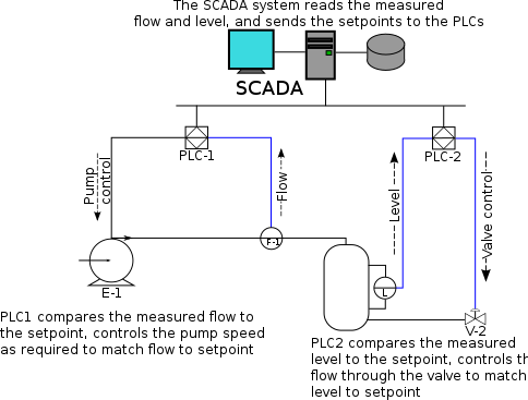
The term SCADA usually refers to centralized systems which monitor and control entire sites, or complexes of systems spread out over large areas (anything between an industrial plant and a country). Most control actions are performed automatically by Remote Terminal Units ("RTUs") or by programmable logic controllers ("PLCs"). Host control functions are usually restricted to basic overriding or supervisory level intervention. For example, a PLC may control the flow of cooling water through part of an industrial process, but the SCADA system may allow operators to change the set points for the flow, and enable alarm conditions, such as loss of flow and high temperature, to be displayed and recorded. The feedback control loop passes through the RTU or PLC, while the SCADA system monitors the overall performance of the loop.


Data acquisition begins at the RTU or PLC level and includes meter readings and equipment status reports that are communicated to SCADA as required. Data is then compiled and formatted in such a way that a control room operator using the HMI can make supervisory decisions to adjust or override normal RTU (PLC) controls. Data may also be fed to a Historian, often built on a commodity Database Management System, to allow trending and other analytical auditing.

SCADA systems typically implement a distributed database, commonly referred to as a tag database, which contains data elements called tags or points. A point represents a single input or output value monitored or controlled by the system. Points can be either "hard" or "soft". A hard point represents an actual input or output within the system, while a soft point results from logic and math operations applied to other points. (Most implementations conceptually remove the distinction by making every property a "soft" point expression, which may, in the simplest case, equal a single hard point.) Points are normally stored as value-timestamp pairs: a value, and the timestamp when it was recorded or calculated. A series of value-timestamp pairs gives the history of that point. It's also common to store additional metadata with tags, such as the path to a field device or PLC register, design time comments, and alarm information.

Human Machine Interface

A Human-Machine Interface or HMI is the apparatus which presents process data to a human operator, and through which the human operator controls the process.

Typical Basic SCADA Animations

An HMI is usually linked to the SCADA system's databases and software programs, to provide trending, diagnostic data, and management information such as scheduled maintenance procedures, logistic information, detailed schematics for a particular sensor or machine, and expert-system troubleshooting guides.

The HMI system usually presents the information to the operating personnel graphically, in the form of a mimic diagram. This means that the operator can see a schematic representation of the plant being controlled. For example, a picture of a pump connected to a pipe can show the operator that the pump is running and how much fluid it is pumping through the pipe at the moment. The operator can then switch the pump off. The HMI software will show the flow rate of the fluid in the pipe decrease in real time. Mimic diagrams may consist of line graphics and schematic symbols to represent process elements, or may consist of digital photographs of the process equipment overlain with animated symbols.

The HMI package for the SCADA system typically includes a drawing program that the operators or system maintenance personnel use to change the way these points are represented in the interface. These representations can be as simple as an on-screen traffic light, which represents the state of an actual traffic light in the field, or as complex as a multi-projector display representing the position of all of the elevators in a skyscraper or all of the trains on a railway.

An important part of most SCADA implementations is alarm handling. The system monitors whether certain alarm conditions are satisfied, to determine when an alarm event has occurred. Once an alarm event has been detected, one or more actions are taken (such as the activation of one or more alarm indicators, and perhaps the generation of email or text messages so that management or remote SCADA operators are informed). In many cases, a SCADA operator may have to acknowledge the alarm event; this may deactivate some alarm indicators, whereas other indicators remain active until the alarm conditions are cleared. Alarm conditions can be explicit - for example, an alarm point is a digital status point that has either the value NORMAL or ALARM that is calculated by a formula based on the values in other analogue and digital points - or implicit: the SCADA system might automatically monitor whether the value in an analogue point lies outside high and low limit values associated with that point. Examples of alarm indicators include a siren, a pop-up box on a screen, or a coloured or flashing area on a screen (that might act in a similar way to the "fuel tank empty" light in a car); in each case, the role of the alarm indicator is to draw the operator's attention to the part of the system 'in alarm' so that appropriate action can be taken. In designing SCADA systems, care is needed in coping with a cascade of alarm events occurring in a short time, otherwise the underlying cause (which might not be the earliest event detected) may get lost in the noise. Unfortunately, when used as a noun, the word 'alarm' is used rather loosely in the industry; thus, depending on context it might mean an alarm point, an alarm indicator, or an alarm event.

Hardware solutions

SCADA solutions often have Distributed Control System (DCS) components. Use of "smart" RTUs or PLCs, which are capable of autonomously executing simple logic processes without involving the master computer, is increasing. A functional block programming language, IEC 61131-3 (Ladder Logic), is frequently used to create programs which run on these RTUs and PLCs. Unlike a procedural language such as the C programming language or FORTRAN, IEC 61131-3 has minimal training requirements by virtue of resembling historic physical control arrays. This allows SCADA system engineers to perform both the design and implementation of a program to be executed on an RTU or PLC. A Programmable automation controller (PAC) is a compact controller that combines the features and capabilities of a PC-based control system with that of a typical PLC. PACs are deployed in SCADA systems to provide RTU and PLC functions. In many electrical substation SCADA applications, "distributed RTUs" use information processors or station computers to communicate with digital protective relays, PACs, and other devices for I/O, and communicate with the SCADA master in lieu of a traditional RTU.

Since about 1998, virtually all major PLC manufacturers have offered integrated HMI/SCADA systems, many of them using open and non-proprietary communications protocols. Numerous specialized third-party HMI/SCADA packages, offering built-in compatibility with most major PLCs, have also entered the market, allowing mechanical engineers, electrical engineers and technicians to configure HMIs themselves, without the need for a custom-made program written by a software developer.

Remote Terminal Unit (RTU)

The RTU connects to physical equipment. Typically, an RTU converts the electrical signals from the equipment to digital values such as the open/closed status from a switch or a valve, or measurements such as pressure, flow, voltage or current. By converting and sending these electrical signals out to equipment the RTU can control equipment, such as opening or closing a switch or a valve, or setting the speed of a pump.

Supervisory Station

The term "Supervisory Station" refers to the servers and software responsible for communicating with the field equipment (RTUs, PLCs, etc), and then to the HMI software running on workstations in the control room, or elsewhere. In smaller SCADA systems, the master station may be composed of a single PC. In larger SCADA systems, the master station may include multiple servers, distributed software applications, and disaster recovery sites. To increase the integrity of the system the multiple servers will often be configured in a dual-redundant or hot-standby formation providing continuous control and monitoring in the event of a server failure.

Operational philosophy

For some installations, the costs that would result from the control system failing are extremely high. Possibly even lives could be lost. Hardware for some SCADA systems is ruggedized to withstand temperature, vibration, and voltage extremes, but in most critical installations reliability is enhanced by having redundant hardware and communications channels, up to the point of having multiple fully equipped control centres. A failing part can be quickly identified and its functionality automatically taken over by backup hardware. A failed part can often be replaced without interrupting the process. The reliability of such systems can be calculated statistically and is stated as the mean time to failure, which is a variant of mean time between failures. The calculated mean time to failure of such high reliability systems can be on the order of centuries.

Communication infrastructure and methods

SCADA systems have traditionally used combinations of radio and direct serial or modem connections to meet communication requirements, although Ethernet and IP over SONET / SDH is also frequently used at large sites such as railways and power stations. The remote management or monitoring function of a SCADA system is often referred to as telemetry.

This has also come under threat with some customers wanting SCADA data to travel over their pre-established corporate networks or to share the network with other applications. The legacy of the early low-bandwidth protocols remains, though. SCADA protocols are designed to be very compact and many are designed to send information to the master station only when the master station polls the RTU. Typical legacy SCADA protocols include Modbus RTU, RP-570, Profibus and Conitel. These communication protocols are all SCADA-vendor specific but are widely adopted and used. Standard protocols are IEC 60870-5-101 or 104, IEC 61850 and DNP3. These communication protocols are standardized and recognized by all major SCADA vendors. Many of these protocols now contain extensions to operate over TCP/IP. It is good security engineering practice to avoid connecting SCADA systems to the Internet so the attack surface is reduced.

RTUs and other automatic controller devices were being developed before the advent of industry wide standards for interoperability. The result is that developers and their management created a multitude of control protocols. Among the larger vendors, there was also the incentive to create their own protocol to "lock in" their customer base. A list of automation protocols is being compiled here.
Recently, OLE for Process Control (OPC) has become a widely accepted solution for intercommunicating different hardware and software, allowing communication even between devices originally not intended to be part of an industrial network.

SCADA architectures

SCADA systems have evolved through 3 generations as follows:

First generation: "Monolithic"

In the first generation, computing was done by mainframe computers. Networks did not exist at the time SCADA was developed. Thus SCADA systems were independent systems with no connectivity to other systems. Wide Area Networks were later designed by RTU vendors to communicate with the RTU. The communication protocols used were often proprietary at that time. The first-generation SCADA system was redundant since a back-up mainframe system was connected at the bus level and was used in the event of failure of the primary mainframe system.

Second generation: "Distributed"

The processing was distributed across multiple stations which were connected through a LAN and they shared information in real time. Each station was responsible for a particular task thus making the size and cost of each station less than the one used in First Generation. The network protocols used were still mostly proprietary, which led to significant security problems for any SCADA system that received attention from a hacker. Since the protocols were proprietary, very few people beyond the developers and hackers knew enough to determine how secure a SCADA installation was. Since both parties had invested interests in keeping security issues quiet, the security of a SCADA installation was often badly overestimated, if it was considered at all.

Third generation: "Networked"

These are the current generation SCADA systems which use open system architecture rather than a vendor-controlled proprietary environment. The SCADA system utilizes open standards and protocols, thus distributing functionality across a WAN rather than a LAN. It is easier to connect third party peripheral devices like printers, disk drives, and tape drives due to the use of open architecture. WAN protocols such as Internet Protocol (IP) are used for communication between the master station and communications equipment. Due to the usage of standard protocols and the fact that many networked SCADA systems are accessible from the Internet, the systems are potentially vulnerable to remote cyber-attacks. On the other hand, the usage of standard protocols and security techniques means that standard security improvements are applicable to the SCADA systems, assuming they receive timely maintenance and updates.

==Trends in SCADA=Reliability Corporation]] (NERC) has specified that electrical system data should be time-tagged to the nearest millisecond. Electrical system SCADA systems provide this Sequence of events recorder function, using Radio clocks to synchronize the RTU or distributed RTU clocks.
SCADA systems are coming in line with standard networking technologies. Ethernet and TCP/IP based protocols are replacing the older proprietary standards. Although certain characteristics of frame-based network communication technology (determinism, synchronization, protocol selection, environment suitability) have restricted the adoption of Ethernet in a few specialized applications, the vast majority of markets have accepted Ethernet networks for HMI/SCADA.

A few vendors have begun offering application specific SCADA systems hosted on remote platforms over the Internet. This removes the need to install and commission systems at the end-user's facility and takes advantage of security features already available in Internet technology, VPNs and SSL. Some concerns include security, Internet connection reliability, and latency.

SCADA systems are becoming increasingly ubiquitous. Thin clients, web portals, and web based products are gaining popularity with most major vendors. The increased convenience of end users viewing their processes remotely introduces security considerations. While these considerations are already considered solved in other sectors of Internet services, not all entities responsible for deploying SCADA systems have understood the changes in accessibility and threat scope implicit in connecting a system to the Internet.

Security issues

The move from proprietary technologies to more standardized and open solutions together with the increased number of connections between SCADA systems and office networks and the Internet has made them more vulnerable to attacks - see references. Consequently, the security of SCADA-based systems has come into question as they are increasingly seen as extremely vulnerable to cyberwarfare/cyberterrorism attacks.

In particular, security researchers are concerned about:
  • the lack of concern about security and authentication in the design, deployment and operation of existing SCADA networks
  • the belief that SCADA systems have the benefit of security through obscurity through the use of specialized protocols and proprietary interfaces
  • the belief that SCADA networks are secure because they are physically secured
  • the belief that SCADA networks are secure because they are disconnected from the Internet

SCADA systems are used to control and monitor physical processes, examples of which are transmission of electricity, transportation of gas and oil in pipelines, water distribution, traffic lights, and other systems used as the basis of modern society. The security of these SCADA systems is important because compromise or destruction of these systems would impact multiple areas of society far removed from the original compromise. For example, a blackout caused by a compromised electrical SCADA system would cause financial losses to all the customers that received electricity from that source. How security will affect legacy SCADA and new deployments remains to be seen.

There are two distinct threats to a modern SCADA system. First is the threat of unauthorized access to the control software, whether it be human access or changes induced intentionally or accidentally by virus infections and other software threats residing on the control host machine. Second is the threat of packet access to the network segments hosting SCADA devices. In many cases, there is rudimentary or no security on the actual packet control protocol, so anyone who can send packets to the SCADA device can control it. In many cases SCADA users assume that a VPN is sufficient protection and are unaware that physical access to SCADA-related network jacks and switches provides the ability to totally bypass all security on the control software and fully control those SCADA networks. These kinds of physical access attacks bypass firewall and VPN security and are best addressed by endpoint-to-endpoint authentication and authorization such as are commonly provided in the non-SCADA world by in-device SSL or other cryptographic techniques.

Many SCADA systems are deployed in critical infrastructures. Attacks to these systems can impact public health and safety. A famous example of a computer-based attack to a SCADA system is the attack carried out on Maroochy Shire Council's sewage control system in Queensland, Australia. Shortly after a contractor had installed the system in January 2000, it began to experience unexplainable problems. Pumps did not run when needed, alarms were not reported, and extensive flooding with sewage occurred in a nearby park and contamination of a river. After careful observation, it was determined that sewage valves were opening of their own accord. This was believed to be a system bug, until careful monitoring of the system logs revealed that these malfunctions were the result of a cyber attack. After 46 reported attacks, the culprit was identified as an disgruntled ex-employee of the contractor company that installed the system, and who was trying to be hired back to solve the problem.

Many vendors of SCADA and control products have begun to address these risks in a basic sense by developing lines of specialized industrial firewall and VPN solutions for TCP/IP-based SCADA networks as well as external SCADA monitoring and recording equipment. Additionally, application whitelisting solutions are being implemented because of their ability to prevent malware and unauthorized application changes without the performance impacts of traditional antivirus scans[citation needed]. Also, the ISA Security Compliance Institute (ISCI) is emerging to formalize SCADA security testing starting as soon as 2009. ISCI is conceptually similar to private testing and certification that has been performed by vendors since 2007. Eventually, standards being defined by ISA99 WG4 will supersede the initial industry consortia efforts, but probably not before 2011.

The increased interest in SCADA vulnerabilities has resulted in vulnerability researchers discovering vulnerabilities in commercial SCADA software and more general offensive SCADA techniques presented to the general security community. In electric and gas utility SCADA systems, the vulnerability of the large installed base of wired and wireless serial communications links is addressed in some cases by applying bump-in-the-wire devices that employ authentication and Advanced Encryption Standard encryption rather than replacing all existing nodes.

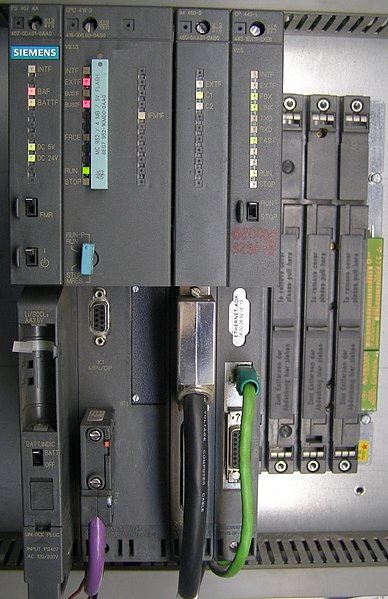
In June 2010, VirusBlokAda reported the first detection of malware that attacks SCADA systems (Siemens' WinCC/PCS7 systems) running on Windows operating systems. The malware is called Stuxnet and uses four zero-day attacks to install a rootkit which in turn logs in to the SCADA's database and steals design and control files. The malware is also capable of changing the control system and hiding those changes. The malware was found by an anti-virus security company on 14 systems with the majority in Iran.

Read more...

DCS


                      A distributed control system (DCS) refers to a control system usually of a manufacturing system, process or any kind of dynamic system, in which the controller elements are not central in location (like the brain) but are distributed throughout the system with each component sub-system controlled by one or more controllers. The entire system of controllers is connected by networks for communication and monitoring.

DCS is a very broad term used in a variety of industries, to monitor and control distributed equipment.

  • Electrical power grids and electrical generation plants
  • Environmental control systems
  • Traffic signals
  • radio signals
  • Water management systems
  • Oil refining plants
  • Chemical plants
  • Pharmaceutical manufacturing
  • Sensor networks
  • Dry cargo and bulk oil carrier ships.

Elements

A DCS typically uses custom designed processors as controllers and uses both proprietary interconnections and communications protocol for communication. Input and output modules form component parts of the DCS. The processor receives information from input modules and sends information to output modules. The input modules receive information from input instruments in the process (a.k.a. field) and transmit instructions to the output instruments in the field. Computer buses or electrical buses connect the processor and modules through multiplexer or demultiplexers. Buses also connect the distributed controllers with the central controller and finally to the Human-Machine Interface (HMI) or control consoles. See Process Automation System.

Elements of a distributed control system may directly connect to physical equipment such as switches, pumps and valves or may work through an intermediate system such as a SCADA system.
A distributed control systen


Applications

Distributed Control Systems (DCSs) are dedicated systems used to control manufacturing processes that are continuous or batch-oriented, such as oil refining, petrochemicals, central station power generation, pharmaceuticals, food & beverage manufacturing, cement production, steelmaking, and papermaking. DCSs are connected to sensors and actuators and use setpoint control to control the flow of material through the plant. The most common example is a setpoint control loop consisting of a pressure sensor, controller, and control valve. Pressure or flow measurements are transmitted to the controller, usually through the aid of a signal conditioning Input/Output (I/O) device. When the measured variable reaches a certain point, the controller instructs a valve or actuation device to open or close until the fluidic flow process reaches the desired setpoint. Large oil refineries have many thousands of I/O points and employ very large DCSs. Processes are not limited to fluidic flow through pipes, however, and can also include things like paper machines and their associated quality controls (see Quality Control System QCS), variable speed drives and motor control centers, cement kilns, mining operations, ore processing facilities, and many others.

A typical DCS consists of functionally and/or geographically distributed digital controllers capable of executing from 1 to 256 or more regulatory control loops in one control box. The input/output devices (I/O) can be integral with the controller or located remotely via a field network. Today’s controllers have extensive computational capabilities and, in addition to proportional, integral, and derivative (PID) control, can generally perform logic and sequential control.

DCSs may employ one or several workstations and can be configured at the workstation or by an off-line personal computer. Local communication is handled by a control network with transmission over twisted pair, coaxial, or fiber optic cable. A server and/or applications processor may be included in the system for extra computational, data collection, and reporting capability.

History

Early minicomputers were used in the control of industrial processes since the beginning of the 1960s. The IBM 1800, for example, was an early computer that had input/output hardware to gather process signals in a plant for conversion from field contact levels (for digital points) and analog signals to the digital domain.

The first industrial control computer system was built 1959 at the Texaco Port Arthur, Texas, refinery with an RW-300 of the Ramo-Wooldridge Company 

The DCS was introduced in 1975. Both Honeywell and Japanese electrical engineering firm Yokogawa introduced their own independently produced DCSs at roughly the same time, with the TDC 2000 and CENTUM systems, respectively. US-based Bristol also introduced their UCS 3000 universal controller in 1975. In 1980, Bailey (now part of ABB) introduced the NETWORK 90 system. Also in 1980, Fischer & Porter Company (now also part of ABB) introduced DCI-4000 (DCI stands for Distributed Control Instrumentation).

The DCS largely came about due to the increased availability of microcomputers and the proliferation of microprocessors in the world of process control. Computers had already been applied to process automation for some time in the form of both Direct Digital Control (DDC) and Set Point Control. In the early 1970s Taylor Instrument Company, (now part of ABB) developed the 1010 system, Foxboro the FOX1 system and Bailey Controls the 1055 systems. All of these were DDC applications implemented within minicomputers (DEC PDP-11, Varian Data Machines, MODCOMP etc.) and connected to proprietary Input/Output hardware. Sophisticated (for the time) continuous as well as batch control was implemented in this way. A more conservative approach was Set Point Control, where process computers supervised clusters of analog process controllers. A CRT-based workstation provided visibility into the process using text and crude character graphics. Availability of a fully functional graphical user interface was a way away.

Central to the DCS model was the inclusion of control function blocks. Function blocks evolved from early, more primitive DDC concepts of "Table Driven" software. One of the first embodiments of object-oriented software, function blocks were self contained "blocks" of code that emulated analog hardware control components and performed tasks that were essential to process control, such as execution of PID algorithms. Function blocks continue to endure as the predominant method of control for DCS suppliers, and are supported by key technologies such as Foundation Fieldbus today.

Midac Systems of Sydney Australia developed an objected-oriented distributed direct digital control system in 1982. The central system ran 11 microprocessors sharing tasks and common memory and connected to a serial communication network of distributed controllers each running two Z80s. The system was installed at the University of Melbourne.

Digital communication between distributed controllers, workstations and other computing elements (peer to peer access) was one of the primary advantages of the DCS. Attention was duly focused on the networks, which provided the all-important lines of communication that, for process applications, had to incorporate specific functions such as determinism and redundancy. As a result, many suppliers embraced the IEEE 802.4 networking standard. This decision set the stage for the wave of migrations necessary when information technology moved into process automation and IEEE 802.3 rather than IEEE 802.4 prevailed as the control LAN.

The Network Centric Era of the 1980s

The DCS brought distributed intelligence to the plant and established the presence of computers and microprocessors in process control, but it still did not provide the reach and openness necessary to unify plant resource requirements. In many cases, the DCS was merely a digital replacement of the same functionality provided by analog controllers and a panelboard display. This was embodied in The Purdue Reference Model (PRM) that was developed to define Manufacturing Operations Management relationships. PRM later formed the basis for ISA95 standards activities today.

In the 1980s, users began to look at DCSs as more than just basic process control. A very early example of a Direct Digital Control DCS was completed by the Australian business Midac in 1981-1982 using R-Tec Australian designed hardware. The system installed at the University of Melbourne used a serial communications network, connecting campus buildings back to a control room "front end". Each remote unit ran 2 Z80 microprocessors whilst the front end ran 11 in a Parallel Processing configuration with paged common memory to share tasks and could run up to 20,000 concurrent controls objects.

It was believed that if openness could be achieved and greater amounts of data could be shared throughout the enterprise that even greater things could be achieved. The first attempts to increase the openness of DCSs resulted in the adoption of the predominant operating system of the day: UNIX. UNIX and its companion networking technology TCP-IP were developed by the Department of Defense for openness, which was precisely the issue the process industries were looking to resolve.

As a result suppliers also began to adopt Ethernet-based networks with their own proprietary protocol layers. The full TCP/IP standard was not implemented, but the use of Ethernet made it possible to implement the first instances of object management and global data access technology. The 1980s also witnessed the first PLCs integrated into the DCS infrastructure. Plant-wide historians also emerged to capitalize on the extended reach of automation systems. The first DCS supplier to adopt UNIX and Ethernet networking technologies was Foxboro, who introduced the I/A Series system in 1987.

The Application Centric Era of the 1990s

The drive toward openness in the 1980s gained momentum through the 1990s with the increased adoption of Commercial off-the-shelf (COTS) components and IT standards. Probably the biggest transition undertaken during this time was the move from the UNIX operating system to the Windows environment. While the realm of the real time operating system (RTOS) for control applications remains dominated by real time commercial variants of UNIX or proprietary operating systems, everything above real-time control has made the transition to Windows.

The introduction of Microsoft at the desktop and server layers resulted in the development of technologies such as OLE for Process Control (OPC), which is now a de facto industry connectivity standard. Internet technology also began to make its mark in automation and the DCS world, with most DCS HMI supporting Internet connectivity. The '90s were also known for the "Fieldbus Wars", where rival organizations competed to define what would become the IEC fieldbus standard for digital communication with field instrumentation instead of 4-20 milliamp analog communications. The first fieldbus installations occurred in the 1990s. Towards the end of the decade, the technology began to develop significant momentum, with the market consolidated around Foundation Fieldbus and Profibus PA for process automation applications. Some suppliers built new systems from the ground up to maximize functionality with fieldbus, such as Honeywell with Experion & Plantscape SCADA systems, ABB with System 800xA, Emerson Process Management with the DeltaV control system, Siemens with the Simatic PCS7 and azbil from Yamatake with the Harmonas-DEO system.

The impact of COTS, however, was most pronounced at the hardware layer. For years, the primary business of DCS suppliers had been the supply of large amounts of hardware, particularly I/O and controllers. The initial proliferation of DCSs required the installation of prodigious amounts of this hardware, most of it manufactured from the bottom up by DCS suppliers. Standard computer components from manufacturers such as Intel and Motorola, however, made it cost prohibitive for DCS suppliers to continue making their own components, workstations, and networking hardware.

As the suppliers made the transition to COTS components, they also discovered that the hardware market was shrinking fast. COTS not only resulted in lower manufacturing costs for the supplier, but also steadily decreasing prices for the end users, who were also becoming increasingly vocal over what they perceived to be unduly high hardware costs. Some suppliers that were previously stronger in the PLC business, such as Rockwell Automation and Siemens, were able to leverage their expertise in manufacturing control hardware to enter the DCS marketplace with cost effective offerings, while the stability/scalability/reliability and functionality of these emerging systems are still improving. The traditional DCS suppliers introduced new generation DCS System based on the latest Communication and IEC Standards, which resulting in a trend of combining the traditional concepts/functionalities for PLC and DCS into a one for all solution—named "Process Automation System". The gaps among the various systems remain at the areas such as: the database integrity, pre-engineering functionality, system maturity, communication transparency and reliability. While it is expected the cost ratio is relatively the same (the more powerful the systems are, the more expensive they will be), the reality of the automation business is often operating strategically case by case. The current next evolution step is called Collaborative Process Automation Systems.

To compound the issue, suppliers were also realizing that the hardware market was becoming saturated. The lifecycle of hardware components such as I/O and wiring is also typically in the range of 15 to over 20 years, making for a challenging replacement market. Many of the older systems that were installed in the 1970s and 1980s are still in use today, and there is a considerable installed base of systems in the market that are approaching the end of their useful life. Developed industrial economies in North America, Europe, and Japan already had many thousands of DCSs installed, and with few if any new plants being built, the market for new hardware was shifting rapidly to smaller, albeit faster growing regions such as China, Latin America, and Eastern Europe.

Because of the shrinking hardware business, suppliers began to make the challenging transition from a hardware-based business model to one based on software and value-added services. It is a transition that is still being made today. The applications portfolio offered by suppliers expanded considerably in the '90s to include areas such as production management, model-based control, real-time optimization, Plant Asset Management (PAM), Real Time Performance Management (RPM) tools, alarm management, and many others. To obtain the true value from these applications, however, often requires a considerable service content, which the suppliers also provide.

Read more...

Thursday, December 16, 2010

PLC


                        A programmable logic controller (PLC) or programmable controller is a digital computer used for automation of electromechanical processes, such as control of machinery on factory assembly lines, amusement rides, or lighting fixtures. PLCs are used in many industries and machines. Unlike general-purpose computers, the PLC is designed for multiple inputs and output arrangements, extended temperature ranges, immunity to electrical noise, and resistance to vibration and impact. Programs to control machine operation are typically stored in battery-backed or non-volatile memory. A PLC is an example of a hard real time system since output results must be produced in response to input conditions within a bounded time, otherwise unintended operation will result.


At rack, left-to-right: power supply unit PS407 4A,CPU 416-3, interface module IM 460-0 and communication processor CP 443-1.

History

The PLC was invented in response to the needs of the American automotive manufacturing industry. Programmable logic controllers were initially adopted by the automotive industry where software revision replaced the re-wiring of hard-wired control panels when production models changed.

Before the PLC, control, sequencing, and safety interlock logic for manufacturing automobiles was accomplished using hundreds or thousands of relays, cam timers, and drum sequencers and dedicated closed-loop controllers. The process for updating such facilities for the yearly model change-over was very time consuming and expensive, as electricians needed to individually rewire each and every relay.

In 1968 GM Hydramatic (the automatic transmission division of General Motors) issued a request for proposal for an electronic replacement for hard-wired relay systems. The winning proposal came from Bedford Associates of Bedford, Massachusetts. The first PLC, designated the 084 because it was Bedford Associates' eighty-fourth project, was the result. Bedford Associates started a new company dedicated to developing, manufacturing, selling, and servicing this new product: Modicon, which stood for MOdular DIgital CONtroller. One of the people who worked on that project was Dick Morley, who is considered to be the "father" of the PLC. The Modicon brand was sold in 1977 to Gould Electronics, and later acquired by German Company AEG and then by French Schneider Electric, the current owner.

One of the very first 084 models built is now on display at Modicon's headquarters in North Andover, Massachusetts. It was presented to Modicon by GM, when the unit was retired after nearly twenty years of uninterrupted service. Modicon used the 84 moniker at the end of its product range until the 984 made its appearance.

The automotive industry is still one of the largest users of PLCs.

Development

Early PLCs were designed to replace relay logic systems. These PLCs were programmed in "ladder logic", which strongly resembles a schematic diagram of relay logic. This program notation was chosen to reduce training demands for the existing technicians. Other early PLCs used a form of instruction list programming, based on a stack-based logic solver.

Modern PLCs can be programmed in a variety of ways, from ladder logic to more traditional programming languages such as BASIC and C. Another method is State Logic, a very high-level programming language designed to program PLCs based on state transition diagrams.

Many early PLCs did not have accompanying programming terminals that were capable of graphical representation of the logic, and so the logic was instead represented as a series of logic expressions in some version of Boolean format, similar to Boolean algebra. As programming terminals evolved, it became more common for ladder logic to be used, for the aforementioned reasons. Newer formats such as State Logic and Function Block (which is similar to the way logic is depicted when using digital integrated logic circuits) exist, but they are still not as popular as ladder logic. A primary reason for this is that PLCs solve the logic in a predictable and repeating sequence, and ladder logic allows the programmer (the person writing the logic) to see any issues with the timing of the logic sequence more easily than would be possible in other formats.
Programming

Early PLCs, up to the mid-1980s, were programmed using proprietary programming panels or special-purpose programming terminals, which often had dedicated function keys representing the various logical elements of PLC programs. Programs were stored on cassette tape cartridges. Facilities for printing and documentation were very minimal due to lack of memory capacity. The very oldest PLCs used non-volatile magnetic core memory.

More recently, PLCs are programmed using application software on personal computers. The computer is connected to the PLC through Ethernet, RS-232, RS-485 or RS-422 cabling. The programming software allows entry and editing of the ladder-style logic. Generally the software provides functions for debugging and troubleshooting the PLC software, for example, by highlighting portions of the logic to show current status during operation or via simulation. The software will upload and download the PLC program, for backup and restoration purposes. In some models of programmable controller, the program is transferred from a personal computer to the PLC though a programming board which writes the program into a removable chip such as an EEPROM or EPROM.

Functionality

The functionality of the PLC has evolved over the years to include sequential relay control, motion control, process control, distributed control systems and networking. The data handling, storage, processing power and communication capabilities of some modern PLCs are approximately equivalent to desktop computers. PLC-like programming combined with remote I/O hardware, allow a general-purpose desktop computer to overlap some PLCs in certain applications. Regarding the practicality of these desktop computer based logic controllers, it is important to note that they have not been generally accepted in heavy industry because the desktop computers run on less stable operating systems than do PLCs, and because the desktop computer hardware is typically not designed to the same levels of tolerance to temperature, humidity, vibration, and longevity as the processors used in PLCs. In addition to the hardware limitations of desktop based logic, operating systems such as Windows do not lend themselves to deterministic logic execution, with the result that the logic may not always respond to changes in logic state or input status with the extreme consistency in timing as is expected from PLCs. Still, such desktop logic applications find use in less critical situations, such as laboratory automation and use in small facilities where the application is less demanding and critical, because they are generally much less expensive than PLCs.

In more recent years, small products called PLRs (programmable logic relays), and also by similar names, have become more common and accepted. These are very much like PLCs, and are used in light industry where only a few points of I/O (i.e. a few signals coming in from the real world and a few going out) are involved, and low cost is desired. These small devices are typically made in a common physical size and shape by several manufacturers, and branded by the makers of larger PLCs to fill out their low end product range. Popular names include PICO Controller, NANO PLC, and other names implying very small controllers. Most of these have between 8 and 12 digital inputs, 4 and 8 digital outputs, and up to 2 analog inputs. Size is usually about 4" wide, 3" high, and 3" deep. Most such devices include a tiny postage stamp sized LCD screen for viewing simplified ladder logic (only a very small portion of the program being visible at a given time) and status of I/O points, and typically these screens are accompanied by a 4-way rocker push-button plus four more separate push-buttons, similar to the key buttons on a VCR remote control, and used to navigate and edit the logic. Most have a small plug for connecting via RS-232 or RS-485 to a personal computer so that programmers can use simple Windows applications for programming instead of being forced to use the tiny LCD and push-button set for this purpose. Unlike regular PLCs that are usually modular and greatly expandable, the PLRs are usually not modular or expandable, but their price can be two orders of magnitude less than a PLC and they still offer robust design and deterministic execution of the logic.

Features

The main difference from other computers is that PLCs are armored for severe conditions (such as dust, moisture, heat, cold) and have the facility for extensive input/output (I/O) arrangements. These connect the PLC to sensors and actuators. PLCs read limit switches, analog process variables (such as temperature and pressure), and the positions of complex positioning systems. Some use machine vision. On the actuator side, PLCs operate electric motors, pneumatic or hydraulic cylinders, magnetic relays, solenoids, or analog outputs. The input/output arrangements may be built into a simple PLC, or the PLC may have external I/O modules attached to a computer network that plugs into the PLC.
Control panel with PLC (grey elements in the center). The unit consists of separate elements, from left to right; power supply, controller, relay units for in- and output

System scale

A small PLC will have a fixed number of connections built in for inputs and outputs. Typically, expansions are available if the base model has insufficient I/O.

Modular PLCs have a chassis (also called a rack) into which are placed modules with different functions. The processor and selection of I/O modules is customised for the particular application. Several racks can be administered by a single processor, and may have thousands of inputs and outputs. A special high speed serial I/O link is used so that racks can be distributed away from the processor, reducing the wiring costs for large plants.

User interface

PLCs may need to interact with people for the purpose of configuration, alarm reporting or everyday control.
A Human-Machine Interface (HMI) is employed for this purpose. HMIs are also referred to as MMIs (Man Machine Interface) and GUIs (Graphical User Interface).

A simple system may use buttons and lights to interact with the user. Text displays are available as well as graphical touch screens. More complex systems use a programming and monitoring software installed on a computer, with the PLC connected via a communication interface.

Communications

PLCs have built in communications ports, usually 9-pin RS-232, but optionally EIA-485 or Ethernet. Modbus, BACnet or DF1 is usually included as one of the communications protocols. Other options include various fieldbuses such as DeviceNet or Profibus. Other communications protocols that may be used are listed in the List of automation protocols.

Most modern PLCs can communicate over a network to some other system, such as a computer running a SCADA (Supervisory Control And Data Acquisition) system or web browser.

PLCs used in larger I/O systems may have peer-to-peer (P2P) communication between processors. This allows separate parts of a complex process to have individual control while allowing the subsystems to co-ordinate over the communication link. These communication links are also often used for HMI devices such as keypads or PC-type workstations.

Programming

PLC programs are typically written in a special application on a personal computer, then downloaded by a direct-connection cable or over a network to the PLC. The program is stored in the PLC either in battery-backed-up RAM or some other non-volatile flash memory. Often, a single PLC can be programmed to replace thousands of relays.
Under the IEC 61131-3 standard, PLCs can be programmed using standards-based programming languages. A graphical programming notation called Sequential Function Charts is available on certain programmable controllers. Initially most PLCs utilized Ladder Logic Diagram Programming, a model which emulated electromechanical control panel devices (such as the contact and coils of relays) which PLCs replaced. This model remains common today.

IEC 61131-3 currently defines five programming languages for programmable control systems: FBD (Function block diagram), LD (Ladder diagram), ST (Structured text, similar to the Pascal programming language), IL (Instruction list, similar to assembly language) and SFC (Sequential function chart). These techniques emphasize logical organization of operations.

While the fundamental concepts of PLC programming are common to all manufacturers, differences in I/O addressing, memory organization and instruction sets mean that PLC programs are never perfectly interchangeable between different makers. Even within the same product line of a single manufacturer, different models may not be directly compatible.

PLC compared with other control systems

PLCs are well-adapted to a range of automation tasks. These are typically industrial processes in manufacturing where the cost of developing and maintaining the automation system is high relative to the total cost of the automation, and where changes to the system would be expected during its operational life. PLCs contain input and output devices compatible with industrial pilot devices and controls; little electrical design is required, and the design problem centers on expressing the desired sequence of operations. PLC applications are typically highly customized systems so the cost of a packaged PLC is low compared to the cost of a specific custom-built controller design. On the other hand, in the case of mass-produced goods, customized control systems are economic due to the lower cost of the components, which can be optimally chosen instead of a "generic" solution, and where the non-recurring engineering charges are spread over thousands or millions of units.

For high volume or very simple fixed automation tasks, different techniques are used. For example, a consumer dishwasher would be controlled by an electromechanical cam timer costing only a few dollars in production quantities.

A microcontroller-based design would be appropriate where hundreds or thousands of units will be produced and so the development cost (design of power supplies, input/output hardware and necessary testing and certification) can be spread over many sales, and where the end-user would not need to alter the control. Automotive applications are an example; millions of units are built each year, and very few end-users alter the programming of these controllers. However, some specialty vehicles such as transit busses economically use PLCs instead of custom-designed controls, because the volumes are low and the development cost would be uneconomic.

Very complex process control, such as used in the chemical industry, may require algorithms and performance beyond the capability of even high-performance PLCs. Very high-speed or precision controls may also require customized solutions; for example, aircraft flight controls.

Programmable controllers are widely used in motion control, positioning control and torque control. Some manufacturers produce motion control units to be integrated with PLC so that G-code (involving a CNC machine) can be used to instruct machine movements.[citation needed]

PLCs may include logic for single-variable feedback analog control loop, a "proportional, integral, derivative" or "PID controller". A PID loop could be used to control the temperature of a manufacturing process, for example. Historically PLCs were usually configured with only a few analog control loops; where processes required hundreds or thousands of loops, a distributed control system (DCS) would instead be used. As PLCs have become more powerful, the boundary between DCS and PLC applications has become less distinct.

PLCs have similar functionality as Remote Terminal Units. An RTU, however, usually does not support control algorithms or control loops. As hardware rapidly becomes more powerful and cheaper, RTUs, PLCs and DCSs are increasingly beginning to overlap in responsibilities, and many vendors sell RTUs with PLC-like features and vice versa. The industry has standardized on the IEC 61131-3 functional block language for creating programs to run on RTUs and PLCs, although nearly all vendors also offer proprietary alternatives and associated development environments.

Digital and analog signals

Digital or discrete signals behave as binary switches, yielding simply an On or Off signal (1 or 0, True or False, respectively). Push buttons, limit switches, and photoelectric sensors are examples of devices providing a discrete signal. Discrete signals are sent using either voltage or current, where a specific range is designated as On and another as Off. For example, a PLC might use 24 V DC I/O, with values above 22 V DC representing On, values below 2VDC representing Off, and intermediate values undefined. Initially, PLCs had only discrete I/O.

Analog signals are like volume controls, with a range of values between zero and full-scale. These are typically interpreted as integer values (counts) by the PLC, with various ranges of accuracy depending on the device and the number of bits available to store the data. As PLCs typically use 16-bit signed binary processors, the integer values are limited between -32,768 and +32,767. Pressure, temperature, flow, and weight are often represented by analog signals. Analog signals can use voltage or current with a magnitude proportional to the value of the process signal. For example, an analog 0 - 10 V input or 4-20 mA would be converted into an integer value of 0 - 32767.

Current inputs are less sensitive to electrical noise (i.e. from welders or electric motor starts) than voltage inputs.

Read more...

Basics of Instrumentation & Control


To view more posts on BASICS : CLICK HERE

Pressure


To view more posts on PRESSURE : CLICK HERE

Flow


To view more posts on FLOW : CLICK HERE

Level


To view more posts on LEVEL : CLICK HERE

Temperature


To view more posts on TEMPERATURE : CLICK HERE

Analytical Instrumentation


To view more posts on Analytical Instrumentation : CLICK HERE
Related Posts Plugin for WordPress, Blogger...

About This Blog

Hai friends…welcome to my blog. This blog is exclusively for instrumentation engineering students which will provide sources for their reference and studies. As you all know Instrumentation is now a fast emerging and developing field in Engineering. This blog has different categories like PLC, SCADA, DCS, Sensors and Transducers, Computer control of process, Industrial Instrumentation, etc.

This blog will also provide an exclusive ‘ASK ME’ section where you can make any queries and share your ideas about instrumentation. The solution for your queries will be given to you by mail from best of my knowledge and reference.

So I wish this blog may be very useful for your studies and reference.

About Me

Keep In Touch

Follow Me!

Online Queries


Popular Posts