Custom Search
RECENT POSTS

Tuesday, February 19, 2019

Ultrasound flowmeters


This method is based on the relationship between the flowrate of the stream and the velocity of ultrasound introduced in this stream. There are several modifications of this method, such as Doppler-effect method and transit-time method. The first one is based on the Doppler effect, saying that frequencies of received waves are dependent on the motion of the source or receiver (observer) relative to the propagating medium. We will describe the second method, which is shown schematically in Fig 6.6.

Figure 6.6. Transit-time flowmeter.


A source of ultrasound 1 is attached outside to the pipe 2 with a flowing fluid 3 inside it. A sonic beam is propagating the flowing fluid at a specific velocity, proportional to the properties of the fluid (temperature, pressure, and density). An ultrasound beam 4 will travel faster in the direction of flow, and slower in the opposite direction. This beam arrives in to the receiver 5 faster than an ultrasound beam 6 from the transmitter 7 to the receiver 8.


Transit time of ultrasound beam from transducer the 1 to the receiver 5 can be evaluated as follows (from Bentley J. P. Principles of Measurement Systems, Longman, 1995, p. 411-412):

(6.46)
Transit time of ultrasound beam from the transducer 7 to the receiver 8 can be evaluated as follows:(6.47)

Let’s evaluate the time difference:

(6.48)

The ratio , therefore,(6.49)


Using (6.49) we can reduce (6.48) to the following form:

(6.50)

where, 


These devices can not be used for flow measurements of fluids with air bubbles or solid particles, since they will interfere with the transmission and receipt of ultrasound radiation. These particles serve as reflectors of ultrasound radiation.

Article Source:: Dr. Alexander Badalyan, University of South Australia

Read more...

Turbine flowmeters


These flowmeters refer to velocity measurement devices, since the action (rotation) of their measuring element (turbine) is proportional to stream velocity, which, in its turn, is proportional to the flow of fluid in the pipe. Turbine flowmeters provide accurate measurements in the wide flow range. However, their application is limited to clean liquids. The name of this device comes from the operational principle of this flowmeter (see Fig. 6.5). 

Fig . 6.5A Basic Parts of the turbine flow meter


The housing of this device 1 is connected to pipes 2 and 3. A turbine 4, sometimes called a rotor, is placed co-axial in this housing in the path of the flowing liquid. This liquid imparts the force to the blades 5 of the rotor and causes the rotor to rotate on the shaft 6, which is connected with the housing by a support 7 with bearings. In order to straighten the stream of the passing fluid, several radial-straightening vanes 8 are placed on the shaft before the rotor in upstream direction. The rotational speed of the rotor is proportional to the fluid velocity only when a steady rotational speed of the rotor has been reached. If we measure the number of turbine wheel revolutions per unit time, then this will be a measure of flowrate. Therefore, we need to measure the number of rotor revolutions. Several methods are used to transmit rotor revolutions through the meter housing to the readout device, which is placed outside the housing. The first method employs a mechanical device, which by use of selected gear trains 9 transmits the rotation of the turbine directly to the register 10. Another, electrical method, employs a permanent magnet with several coils mounted close to the rotor but external to the fluid channel. When one blade of the rotor passes the coil, the total flux through the coil changes and a pulse of voltage is generated (one cycle of voltage). The frequency of voltage pulses is proportional to the fluid flowrate, and the total number of pulses is an indicator of the total flow.


Figure 6.5. Turbine flowmeter.

Article Source:: Dr. Alexander Badalyan, University of South Australia

Read more...

Venturi flow nozzle


There is another modification of the variable differential pressure technique for flowrate measurements. This technique employs a Venturi flow nozzle, which is shown schematically in Fig. 6.4. 


The Venturi flow nozzle is installed in pipes with internal diameter varying from 65 to 500 mm. It produces a large differential pressure with a minimum loss of static pressure. This nozzle is able to measure flowrates of fluids with suspended solids. However, Venturi flow nozzles are very expensive. It consists of three parts: a profiled inlet 1, a cylindrical throat 2, and a conical outlet 3. A pipes 4 and 5 are connected to the inlet and outlet of the Venturi flow nozzle. The nozzle may be long and short. In the first case the biggest diameter of the outlet cone Dcmax is equal to the internal diameter of the pipe  Dp, in the second case it is less than Dp. The restriction diameter of Venturi flow nozzles Dn ³ 15 mm. The differential pressure is measured as in the case for orifice flowmeters with the only difference, that the downstream pressure in the cylindrical throat is sensed through radially drilled holes 6.

Figure 6.4. Venturi flow nozzle.


Article Source:: Dr. Alexander Badalyan, University of South Australia

Read more...

Saturday, February 16, 2019

Rotameters


This type of device (see Figure 6.3) consists of a vertical tapered tube 1 (usually made of a glass or other transparent material) and a rotor 2 (or a float), usually made of a metal (aluminium, brass, stainless steel, etc.) with higher density than that of a fluid 3 being measured. 


The rotor is produced with slots to give it rotation, so the rotor can be placed co-axial inside the tube. When the flowrate of the fluid through the tube increases the rotor is elevated upwards until the balance between forces acting on the rotor is achieved. Since the tube is tapered, then the restriction area (the area between the wall of the tube and side surface of the float) will change to accommodate flow rate being measured. Therefore, for each value of the flowrate will correspond certain position of the rotor in the tube in respect to a scale 4 and a certain value of the restriction area. 
Figure 6.3. Variable area flowmeter (rotameter).


Let's consider forces acting on the rotor during balance:

 (6.40)

or

(6.41)
(6.42)
(6.43)

where,


Equation (6.43) shows that the difference of pressures is constant and is not a function of a flowrate. Therefore, this type of device sometimes is called the flowmeter with constant differential pressure.

An equation for the evaluation of the volumetric flowrate (m3/s) has final form as follows:

(6.44)

where,

ฯ†         -- discharge coefficient taking into account friction of the fluid with the rotor and the tube, pressure losses due to vortex of fluid under and above the rotor, and changes of the stream form when it passes through the restriction area between the rotor and the tube;

Sgap    --the area of an annular gap (restriction) between the rotor and the wall of the tube, m2.

Sgap  is defined by the geometry of the float and pipe as follows:

(6.45)

where,


The accuracy of rotameters varies from±0.25 to ±2% (for individual calibration). Their repeatability is excellent. They can measure flowrates from 0.5 cm3/min to 1135 l/min of water.


Article Source:: Dr. Alexander Badalyan, University of South Australia

Read more...

Tuesday, February 12, 2019

Orifice plates


This method is based in the phenomenon that a stream of fluid (liquid, gas or vapour) when passing through the restriction or primary device (orifice plate, Venturi plate, flow nozzle, etc.) is subjected to the change of kinetic and potential energy of the stream during variations of flowrate. Figure 6.1 shows an orifice plate. 

Let’s consider two cases with incompressible and compressible fluids.


Case 1. Incompressible fluid.

The following assumptions should be considered when derive working equations:

1 - fluid is incompressible, and there are no phase changes when fluid passes through the orifice;

2 - fluid flow is steady and frictionless, ie. there are no energy losses due to friction;

3 - flow is isothermal, ie. no heat losses or gains due to heat transfer between the fluid and its surroundings;

4 - there is no in and outflow of energy between sections A  -  A  and B - B;

5 - mass flowrates in each cross-section of the stream is constant;

6 - pipe is horizontal.

Figure 6.1. Orifice plate. (from Bentley J. P. Principles of Measurement Systems, Longman, 1995, p. 286):

An equation for conservation of mass flowrate is as follows:

   (6.1)

Since 
               (6.2)

then, we can give an equation for conservation of volumetric flowrate
   (6.3)

When a volumetric flow rate in a pipe (see Figure 6.2) increases, then the velocity of the fluid through the orifice should increase as well. Since SA>SB , then  vA<vB. Due to inertia the smallest cross-section area of the stream is not in the plane of the orifice itself, but some distance downstream from it. The total energy of the stream is equal to the sum of its kinetic energy and static head of the stream.

Figure 6.2. Orifice-type differential pressure flowmeter.

Since the kinetic energy increases (due to the increasing of the velocity of the stream in cross-section B - B), then the static head should decrease. This static head is responsible for the static pressure of the stream. Therefore, there is a head difference in two cross-sections (ฮ”P=PA-PB), namely the differential pressure, which is the function of the velocity and finally of the flowrate of the stream. It means that for each value of the flowrate corresponds a certain value of a differential pressure. Therefore, we can measure this differential pressure and, finally, evaluate the required value of the flowrate. 

Equations for potential and kinetic energies of the fluid stream and work performed by it are as follows (from Bentley J. P. Principles of Measurement Systems, Longman, 1995, p. 280):


Combine equations (6.4) - (6.5) and get an equation for the conservation of the total energy per unit mass of the stream for the case of two cross-sections A  -  A  and B - B:

(6.7)
or, since the pipe is horizontal (the assumption 6)

then 

From equation (6.9) we can get an expression for the velocity of the stream in the cross-section B - B:

A theoretical equation for the flow of a fluid is as follows:

(6.12)

Frictionless flow is only approached at well-established turbulent flows. We are not able to measure SAand SB, which vary with the variation of fluid flowrate. So, we need to modify equation (6.12) and get a practical equation for the evaluation of fluid volumetric flowrate:

(6.13)
In the above equations we used the following parameters:


Case 2. Compressible fluid.

 
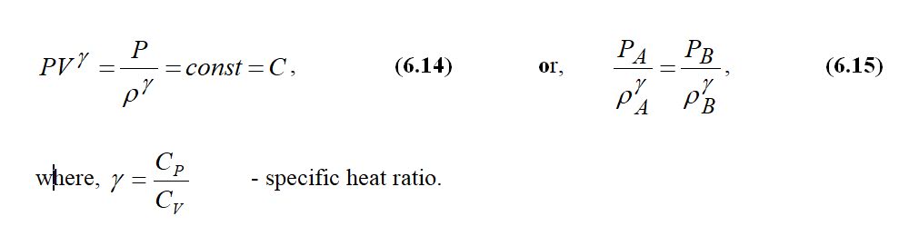
In this case the density of a fluid depends on pressure in the form (from Bentley J. P. Principles of Measurement Systems, Longman, 1995, p. 287):

From (6.14) we have:
Let’s integrate an expression  
 Then: 
Now we can re-write Bernoulli equation in the following form:

(6.16)
or, since zA=zB then,

(6.17)
During the flow of a compressible fluid we have:


(6.18)
and therefore,  
(6.19)

So, 
(6.20)
and 
(6.21)

Therefore, mass flowrate is used in gas metering. A theoretical equation for a compressible flow has the following form:

(6.22)

A practical equation for a compressible flow has the following form:

(6.23)

where, the expansibility factor has the following form according to BS 1041 and ISO 5167 (from Bentley J. P. Principles of Measurement Systems, Longman, 1995, p. 288):

(6.24)
For liquids   ๊œซ =1.0     

Below are given equations and data, which should be used during calculations of flowrates when orifice plates are used.

Discharge coefficient data for orifice plate, BS 1042.

The Stolz equation:

(6.25)
If
(6.26)
then, 
(6.27)
For corner tappings:

(6.28)
For flange tappings:
(6.29)

a). Conditions of validity for corner taps:

b). Conditions of validity for flange taps:


To calculate the value of Dor one need to perform several iterations until this value is obtained with the accuracy equal to the tolerance  ฮด  of machining of the surface of an orifice.

Step 1. Calculate Re.
Step 2. Set initial guess for parameters as follows: C=0.6, ๊œซ =1.0 , E=1.0
Step 3. Calculate area Sor of the orifice hole using (6.13) or (6.23) and value of maximum flowrate.
Step 4. Calculate Dor.
Step 5. Calculate ฮฒ.
Step 6. Revise the value of E according to 


Step 7. If we have liquid, then ๊œซ =1.0. Evaluate C according to (6.25). Then continue starting from step 3, and so on.
Step 8. If we have gas, then if

evaluate ๊œซ according to (6.24). Evaluate C according to (6.25). Then continue starting from step 3, and so on.
Step 9. Check if Dor. >=12.5mm .
Step 10. Check if final values of ฮฒ and Re are within limits.

Article Source:: Dr. Alexander Badalyan, University of South Australia

Read more...

Basics of Instrumentation & Control


To view more posts on BASICS : CLICK HERE

Pressure


To view more posts on PRESSURE : CLICK HERE

Flow


To view more posts on FLOW : CLICK HERE

Level


To view more posts on LEVEL : CLICK HERE

Temperature


To view more posts on TEMPERATURE : CLICK HERE

Analytical Instrumentation


To view more posts on Analytical Instrumentation : CLICK HERE
Related Posts Plugin for WordPress, Blogger...

About This Blog

Hai friends…welcome to my blog. This blog is exclusively for instrumentation engineering students which will provide sources for their reference and studies. As you all know Instrumentation is now a fast emerging and developing field in Engineering. This blog has different categories like PLC, SCADA, DCS, Sensors and Transducers, Computer control of process, Industrial Instrumentation, etc.

This blog will also provide an exclusive ‘ASK ME’ section where you can make any queries and share your ideas about instrumentation. The solution for your queries will be given to you by mail from best of my knowledge and reference.

So I wish this blog may be very useful for your studies and reference.

About Me

Keep In Touch

Follow Me!

Online Queries


Popular Posts